|
|
|
|
|
|
|
|
|
|
|
|
|
|
|
|
|
|
|
|
|
|
|
|
|
|
AWARNING: This machine contains sharp knives, rotating parts, and voltнages dangerous to life. Only qualified trained personnel should perform mainнtenance duties on this machine. Before opening or removing any cover or guard always turn the power disconнnect/lockout switch to "O" (OFF) and lock out power source. After machine has come to a complete stop, press the "I" (START) button to verify machine will not start. Follow all safety rules and instructions outlined in this manual, or serious injury such as amputation or death could result!
|
|
|
|
|
|
|
|
|
|
|
|
|
|
|
|
|
|
|
|
|
|
|
|
|
|
|
|
|
MAINTENANCE
Covers and Guards
|
|
|
|
|
|
|
|
OPENING OR REMOVING
A WARNING: Before opening or removing any cover or guard always turn the power disconnect/ lockout switch to "O" (OFF) and lock out power source. After machine has come to a complete stop, press the "I" (START) button to verify machine will not start. Do not attempt to operate this machine if any cover or guard is opened or removed. Operating the machine with covers or guards opened or removed may result in serious injury such as amputation!
Open or remove the following covers and guards to service the various areas of the machine (Figure 19, page 37).
Feed hopper assembly: Rotate into maintenance position to access cutting parts.
Upper discharge chute: Remove to access cutting parts.
Lower discharge chute: Remove to access impeller drive assembly.
Frame cover: Remove to service drive parts.
Belt guards: Remove to service drive parts.
|
|
|
|
|
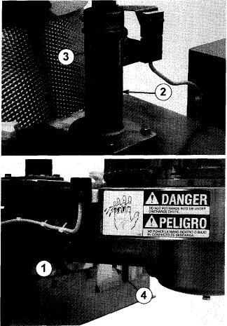
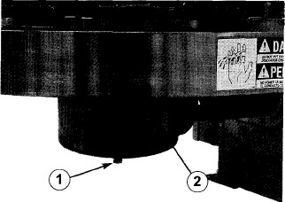
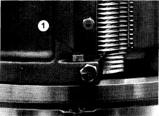
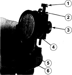
Figure 18 Ч Safety switch sensors and actuators must be aligned and within 1/16" (1.6 mm). (1) Sensor, (2) Actuator
|
|
|
|
INSPECTION
Inspect all covers and guards for damage. Bent or twisted parts will not fit on the machine properly and may prevent safety switches from lining up. Straighten parts or replace if necessary.
|
|
|
|
INSTALLATION
Replace all covers and guards in their proper locations; replace fasteners and tighten securely. Covers and guards equipped with safety switches must have actuators aligned and within 1/16" (1.6 mm) of sensors to complete safety switch circuit (Figure 18).
|
|
|
|
|
|
|
|
|
|
|
|
|
|
|
|
|
|
|
|
|
|
|
|
|
|
|
|
|
MAINTENANCE
Covers and Guards
|
|
|
|
|
|
|
|
|
|
|
|
|
|
|
|
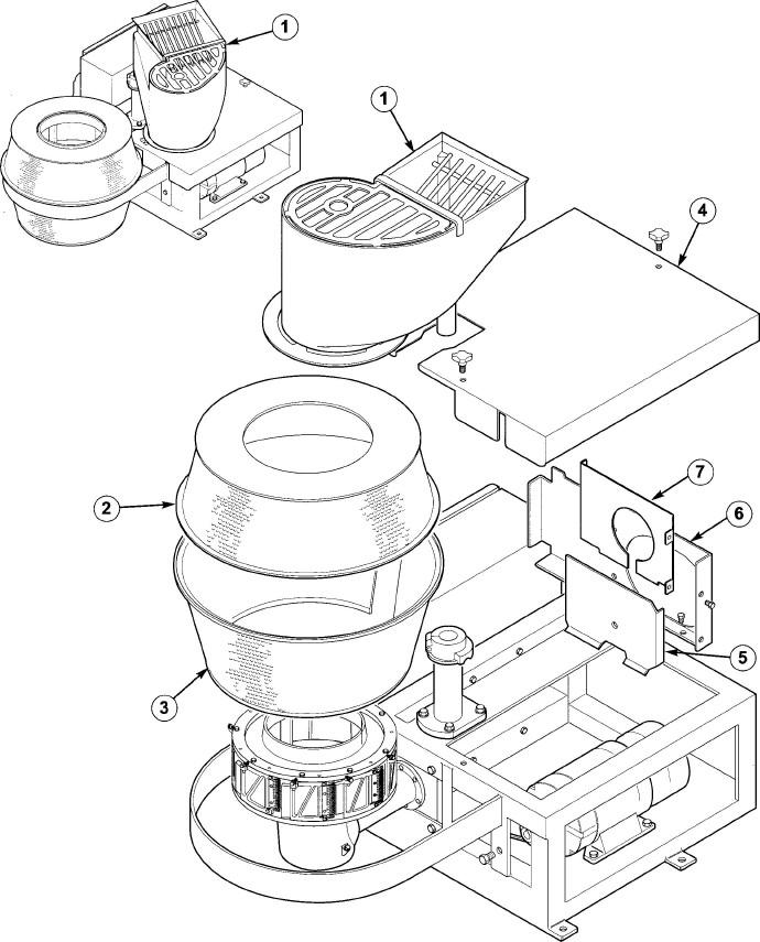
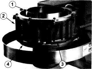
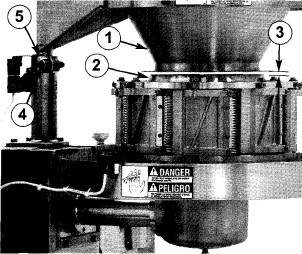
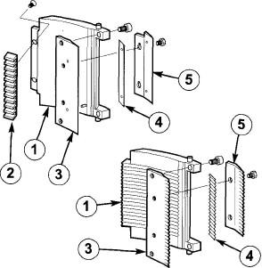
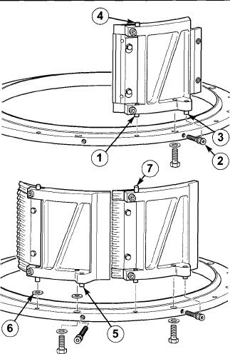
Figure 19 Ч Covers and guards. (1) Feed Hopper, also shown at upper left rotated into maintenance position, (2) Upper Discharge Chute, (3) Lower Discharge Chute, (4) Frame Cover, (5) Belt Guard, (6) Belt Guard, inner, (7) Belt Guard, insert
37
|
|
|
|
|
|
|
|
|
|
|
|
|
|
|
|
|
|
|
|
|
MAINTENANCE
Cleaning______
|
|
|
|
|
|
|
|
IMPORTANCE OF DAILY CLEANING DAILY CLEANING PROCEDURES
|
|
|
|
|
|
|
|
Stainless steel and manganese aluнminum bronze parts will corrode if salty and acidic product juices are not removed completely. Also, product that remains in the cutting unit may harden making future cleaning difficult and encouraging bacterial growth. Heavy product build-up on cutting parts can reduce cutting efficiency and cause the loss of critical tolerances and clearances.
CLEANING AGENTS
The selection of cleaning agents or their solution strength will depend on the appliнcation or process in which the machine is involved. Consult your cleaning materials supplier for selecting and using the proper cleaning agent to meet the sanitizing requirements for your process. Cleaning supplies should be suitable for use with 300 and 400 series stainless steel and manganese aluminum bronze alloy. Excessive solution strength and soaking time or excessive soaking time alone may chemically harm or destroy these and other materials. Solutions containing chloнrine or acids can also be harmful. Failure to completely remove these chemicals with an appropriate rinse will cause corroнsion.
|
Only qualified trained personnel should clean the machine. Consult your company policy regarding proper cleaning/sanitizing solutions and required frequency of cleaning.
NOTE: Never use abrasives, metal tools, wire brushes or sandpaper to clean any parts. Scrape with wooden or plastic tools if necessary.
1. Clean outside of machine with water.
NOTE: Do not direct a stream of water at the starter enclosure or electrical conнnections. Water entering the starter encloнsure could cause electrical failure and void the warranty.
2. Flush product from cutting parts.
Direct a stream of water or cleaning solution into feed opening while machine is running.
A WARNING: Make certain that all covers and guards are in place while machine is running! Maintain a safe distance from machine. Do not insert hose or cleaning tools into feed opening!
|
|
|
|
|
|
|
|
|
|
|
|
|
|
|
|
|
|
|
|
|
|
|
|
|
|
|
|
|
|
MAINTENANCE
Cleaning and Safety Signs
|
|
|
|
|
|
|
|
3. Stop the machine. Turn power disнconnect/lockout switch to "O" (OFF) and lock out. After machine has come to a complete stop, press the "I" (START) button to verify machine will not start before opening or removing any cover or guard.
4. Rotate feed hopper into mainteнnance position and remove upper discharge chute, lower discharge chute and cutting head assembly. Always rest cutting head upside down on a soft surface, never on the dowel pins. Thorнoughly wash all sheet metal covers (see "Opening or Removing", page 36.)
5. Remove and disassemble the cutting head. See "Disassembly", pages 42 and 44. Remove shoes. Disнassemble shoes by removing knife holders, knife clamps, knives and gate insert strips if applicable. Thoroughly wash all cutting parts and impeller with water or appropriate cleaning solution. If cleaning solutions are used, rinse thoroughly.
6. Remove impeller. See "Disassembly", page 42.
7. Clean remaining portion of machine.
A forceful stream of water will remove most of the product. Use cleaning soluнtions when necessary and rinse thorнoughly.
|
SAFETY SIGNS
A WARNING: Safety signs are placed on machines to help users avoid perнsonal injury. If the machine does not have these signs or if they are no longer legible do not use the machine. Install or replace the signs immediately.
INSPECTION
Safety signs: Inspect all safety signs on machine for damage. Damaged, loose, illegible or missing signs must be replaced. See "Safety Signs and Machine Labels", pages 140-141 for sign placement and part number information.
INSTALLATION
1. Clean mounting surfaces. Remove all traces of old sign material and adhe-sives, oils, cleaning material and water. Remove any nicks or burrs. For machines in cold room temperature, warm the mounting surface so that the label will adhere properly.
2. Wipe mounting surface of machine
with isopropyl alcohol. (Consult manuнfacturer's Material Safety Data Sheet for proper handling of isopropyl alcohol.) Remove sign backing and apply label to dry, lint free mounting surface, starting at one end of label and rolling to other end to help avoid air bubbles. For maximum bond strength, rub mounted label with a clean dry cloth and apply moderate heat (100-130°F, 38-54°C).
|
|
|
|
|
|
|
|
|
|
|
|
|
|
|
|
|
|
|
|
|
|
|
|
|
|
|
|
|
|
|
|
|
|
|
|
|
|
RECOMMENDED LUBRICANT
Use a food grade lubricant that is non-toxic, sanitary and approved for incidental food contact. The lubricant recommended for this machine, except motor, is Haynes® Lubri-Film (listed as H-1 by the USDA) available in grease cartridges. Keystone KLC®-20 oil, available in five gallon cans, is recommended for the gear case. The lubricant and oil may be purнchased from Urschel Laboratories. See "Tools", page 73.
|
|
|
|
|
LUBRICATION POINTS
The machine has four (4) lubrication points. Grease fittings are located on the impeller drive assembly (Figure 20) and the rotating hopper assembly. The third point is on the top of the hopper stop. The fourth lubrication point is at the oil filler plug in the gear case (Figure 21).
|
|
|
|
|
|
|
|
Figure 20 Ч Lubrication Points. (1, 2) Grease Fitнtings, (3) Hopper Stop (4) Pipe Plug, horizontal bearing housing
|
|
|
|
|
|
|
|
|
|
|
|
|
|
|
|
|
|
|
|
|
|
|
|
|
|
|
|
|
|
|
|
|
|
|
|
|
|
LUBRICATION SCHEDULE
1. After each cleaning, grease the top of the hopper stop (Figure 20).
2. At least once per week, remove the pipe plug in the horizontal bearing housing (Figure 20) and pump grease in through the fitting until any water is forced out. Replace the pipe plug and add two or three pumps of grease to fill the bearings. Also lubricate the rotating hopper through the grease fitting.
3. Every two weeks, remove the pipe plug and drain the gear case (Figure 21). Check for the presence of water; oil will have a "milky" appearance. If little or no water is present, the check can be made every three or four weeks. Refill with the recommended oil through the oil filler plug on the side of the gear case. Mainнtain a level up to the fill hole.
|
|
|
|
|
Figure 21 Ч Gear case. (1) Pipe Plug, gear case, (2) Oil Filler Plug (bronze assembly)
|
|
|
|
|
|
|
|
MOTOR LUBRICATION
Lubricate according to the motor manuнfacturer's instructions which are supplied with this machine.
|
|
|
|
|
|
|
|
|
|
|
|
|
|
|
|
|
|
|
|
|
|
|
|
|
|
|
|
|
|
MAINTENANCE
Cutting Unit____
|
|
|
|
|
|
|
|
DISASSEMBLY
A WARNING: Cutting head contains sharp knives! Use extreme caution when handling cutting parts or perнsonal injury can occur.
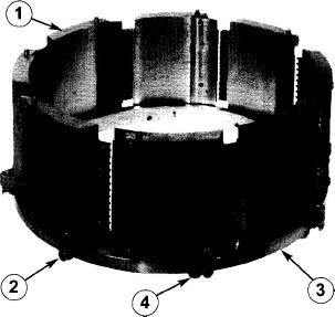
The cutting unit consists of the cutting head assembly, impeller and cutting head support. To disassemble, refer to Figure 22 and proceed as follows:
1. Disconnect and lock out power source. After machine has come to a complete stop, press the "I" (START) button to verify machine will not start. Rotate feed hopper into maintenance position, then remove upper and lower discharge chutes.
2. Remove cutting head. Grasp firmly with both hands and lift straight up. Some cutting heads are held to the support by two hold down screws through opposite shoes (Figure 23). Remove these screws first. Always store the cutting head upside down on a soft surface, never on the dowel pins.
NOTE: DO NOT use the aluminum shipping plate for storage purposes. Elecнtrolytic action between aluminum plate and shoes may cause serious corrosion. Mount cutting head on this plate for protection if it is being returned to factory for repairs.
3. Remove impeller. Unfasten the three screws in bottom plate and lift from impeller shaft.
4. Remove cutting head support from gear case by unfastening the eight (8) screws. Cutting head support does not need to be removed to inspect dowel pin holes. See "Inspection", which follows.
|
|
|
|
|
Figure 22 Ч Cutting unit. (1) Impeller, (2) Cutting Head Assembly, (3) Shoe, (4) Cutting Head Support
|
|
|
|
|
|
|
|
Figure 23 Ч Cutting head hold down screw. (1) Hold Down Screw
|
|
|
|
INSPECTION
All parts should be cleaned, inspected for serviceability, and repaired or replaced if necessary.
Cutting head: Inspect locating surface of each shoe for nicks, burrs, or foreign material which could prevent head from resting uniformly on cutting head support. Clean and hone as necessary. Also see "Inspection", page 45.
|
|
|
|
|
|
|
|
|
|
|
|
|
|
|
|
|
|
|
|
|
|
|
|
|
|
|
|
|
|
MAINTENANCE
_____Cutting Unit
|
|
|
|
|
|
|
|
Impeller: When impeller paddles have worn to a point where cutting quality is unacceptable, replace impeller or paddles. Bolted in paddles on standard stainless steel impellers can be reversed or flipped to make use of all four edges. When outside diameter on the impeller's top plate has worn to a sharp edge, impeller must be replaced.
Cutting head support: If holes for dowel pins are worn to .255" (6.477 mm) diameter or more, shoes will move out of proper position, causing a poor quality cut. Check hole size using pin gauge supplied with machine, (see "Tools", page 73). If pin goes into hole past the chamfer, cutting head support should be returned to the factory for repair, or replaced. Check top surface for flatness and any raised areas. Return to factory for repair or replace.
REASSEMBLY
1. Make sure all mating surfaces are clean and free of burrs.
2. Install cutting head support. Place support on gear case and fasten with the eight (8) screws. Use Permatex® Aviation Form-A-Gasket® sealant on the screws to keep water out of gear case.
3. Install impeller. Carefully place impeller on impeller shaft dowel pin, aligning the three screw holes. Install lightly greased (food grade) screws and tighten.
4. Install cutting head. Carefully lower head onto support. Slowly rotate head clockwise until dowel pins drop into holes. If there is any free movement of
|
|
|
|
|
Figure 24 Ч Centering feed hopper. (1) Feed Hopper, (2) Impeller, (3) 5/32" (4.00 mm) Clearance, (4) Pinch Bolt, (5) Stop Collar
head on support, inspect holes and locating pins for correct size. Install hold down screws and lock nuts on cutting heads equipped with these fasteners.
5. Replace lower and upper discharge chutes. Handle sheet metal parts careнfully. Rotate feed hopper back into operнating position.
ADJUSTMENTS
Feed hopper alignment: Feed hopper should always be centered over impeller with approximately 5/32" (4.0 mm) clearнance from top of impeller to bottom of feed hopper (Figure 24). If not aligned, small pieces of product may be sheared off on impeller rim. To adjust, rotate feed hopper into maintenance position and remove upper discharge chute (see "Covers and Guards", page 36). Loosen pinch bolt on stop collar, position feed hopper until cenнtered with proper clearance and retighten pinch bolt. Replace upper discharge chute and rotate feed hopper back into operating position.
|
|
|
|
|
|
|
|
|
|
|
|
|
|
|
|
|
|
|
|
|
|
|
|
|
|
|
|
|
|
MAINTENANCE
Cutting Heads
|
|
|
|
|
|
|
|
|
|
|
|
|
|
|
|
|
Figure 25 Ч Cutting head upside down for mainteнnance. (1) Shoe, (2) Adjusting Screw, (3) Top Support Ring, (4) Fastener for Shoe
|
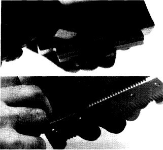
Figure 26 Ч Typical cutting shoes: slicing shoe with gate (top); shredding shoe, gateless (bottom). (1) Shoe, (2) Gate Insert Strip, (3) Knife Holder, (4) Knife, (5) Knife Clamp
|
|
|
|
|
|
|
|
DISASSEMBLY
1. Disconnect and lock out power source. After machine has come to a complete stop, press the "I" (START) button to verify machine will not start. Remove cutting head and place upside down on a work surface. See "Disasнsembly", page 42.
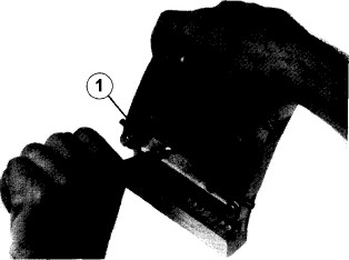
2. Remove shoes. Extend the cutting head a safe distance beyond the edge of the work bench, enough to allow access to the fastener that holds one shoe (Figure 25). Unfasten the screw and remove the shoe. Rotate the head, removing each shoe. Shred head shoes are alternately attached with spacers to raise every other shoe.
NOTE: Keep these spacer washers separate from the washers used with fasteners to attach shoes.
|
3. Remove knife clamps and knives.
Two fasteners hold knife clamp to knife holder (Figure 26). Note that wide oval shoes do not have clamps.
4. Remove knife holder and gate insert strip. Two screws fasten knife holder to shoe. Note that some shredding shoes do not have gate insert strips.
|
|
|
|
INSPECTION
All parts should be cleaned, inspected for serviceability, and repaired or replaced if necessary.
Knives: These knives are intended to be replaced when dull or damaged.
|
|
|
|
|
|
|
|
|
|
|
|
|
|
|
|
|
|
|
|
|
|
|
|
|
|
|
|
|
|
MAINTENANCE
Cutting Heads
|
|
|
|
|
|
|
|
Top support ring: Clean mating surface; hone off any burrs. If holes for pivot pins are worn to .252" (6.401 mm) diameter or more, ring should be replaced. Measure with standard "small-hole" gauge and micrometer. If ring has been dropped or you suspect damage, return ring to factory for inspection.
Knife clamps: Clean with water and a stiff bristle brush. Check for straightness with steel ruler along inner surface of clamp. Compare clamps with profile of an unused clamp.
Gate insert strip: Check for wear. This part can be turned or reversed on certain shoes, see "Reassembly", page 46.
Knife holders: Clean with water and a stiff bristle brush. Check for straightness with steel ruler along inner surface of holder. Compare holders with profile of an unused holder. If knife holder is badly nicked, replace it. Do not attempt repair.
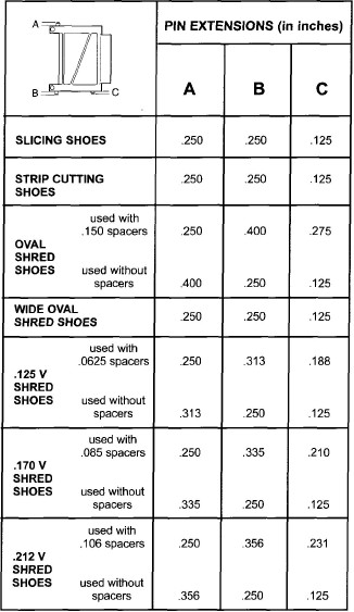
Shoes: Clean mating surfaces and hone off any burrs. Inspect dowel pins for wear, replacing only when absolutely necнessary. When installing new pins, the .125" or .250" dowel pin gauge block (see "Tools", page 73) should be used either alone or in combination with the shredding shoe spacer to measure proper pin extension (Figure 27). Shoes with loose pins should be replaced.
Check for shoe wear by placing a steel ruler on the inner surface of the shoe from top to bottom. If the gap at the mid point of the ruler is .002" (.051 mm) or greater, replace the shoe. If inner surface of shoe wears below knife holder or gate extension strip, shoes should be replaced. If there is a gap between slicing shoe and knife holder (or gate extension strip) measuring .002" (.051 mm) or greater, replace shoe.
|
|
|
|
|
Figure 27 Ч Pin extension chart
NOTE: .125 shred shoes are used to obtain .070 full and V shred cut sizes, . 170 shred shoes are used to obtain .097 full and V shred cut sizes, and .212 shred shoes are used to obtain . 125 full and V shred cut sizes. See "Cutting Heads", pages 116-122.
|
|
|
|
|
|
|
|
|
|
|
|
|
|
|
|
|
|
|
|
|
|
|
|
|
|
|
|
|
|
MAINTENANCE
Cutting Heads
|
|
|
|
|
|
|
|
REASSEMBLY
1. Place a small amount of grease (food grade) on the fasteners to make future removal easier.
2. Install gate insert strip (shoes with gate insert strips only) with small chamнfered corner facing slicing shoe. SLICING HEADS Ч turn insert around if trailing edge has become rounded. STRIP CUTTING HEADS Ч cannot be reversed. Fasten with screws, holding insert firmly against its seat. Check for proper seat with .0015" feeler gauge supplied with machine (Figure 28). Gauge should not fit between the two mating surfaces.
3. Install knife holder. Fasten to shoe with screws, making sure holder is firmly against its seat while tightening. Check for proper seat with .0015" feeler gauge supplied with machine (Figure 28). Gauge should not fit between the two mating surfaces.
4. Install knife. FLAT KNIVES Ч locate on the two pins on knife holder, either side up. CRINKLE OR V-CUT KNIVES Ч center knife on knife clamp. It will not -center if knife is upside down. STRIP CUTTING KNIVES Ч install flat knife then place longer strip cutting knife over shorter knife and locate on pins. WIDE OVAL KNIVES Ч fasten to shoe with screws, making sure knife is firmly against its seat while tightening. Check for proper seat with .0015" feeler gauge supplied with machine. Gauge should not fit between the two mating surfaces. Wide oval shred assemblies do not have knife holders or knife clamps.
|
|
|
|
|
Figure 28 Ч Checking seat on gate insert strip (top) and knife holder (bottom)
|
|
|
|
|
|
|
|
Figure 29 Ч Installing knife and knife clamp and tightening screws. (1) Knife Clamp
5. Install knife clamp. FLAT KNIVES Ч fasten clamp over knife and tighten the two screws alternately until they stop. Clamp pressure should force knife into radius of holder. CRINKLE OR V-CUT KNIVES Ч place knife and clamp together on knife holder. Install and lightly tighten screws. Use wood block provided to hold knife tightly against its seat while tightening screws (Figure 29) until they stop Ч 45-50 inch pounds (5.08-5.65 newton-meters).
|
|
|
|
|
|
|
|
|
|
|
|
|
|
|
|
|
|
|
|
|
|
|
|
|
|
|
|
|
|
MAINTENANCE
Cutting Heads
|
|
|
|
|
|
|
|
6. Turn adjusting screws until inside shoulнder is 1/16" (1.6 mm) from top support ring (Figure 30).
7. Install preassembled shoes. Set pivot pin in proper hole with adjustment pin between shoulders of the adjusting screw.
NOTE: On shred heads, every other shoe will have longer extension on the pivot and adjustment pins. Install these shoes with the proper spacers. See Figure 27, page 45.
8. Fasten shoes from bottom of ring with screw and special washer. Tighten screw enough to hold shoe firmly, but loose enough to make slice thickness adjustment.
NOTE: Cutting head assemblies with hold down screws must have the two shoes without locating pins installed opposite each other on the top support ring. Hold down screws fasten the cutting head to the cutting head support. See items 9 and 10, page 125.
|
|
|
|
|
Figure 30 Ч Installing slicing shoes (top) and shredнding shoes (bottom). (1) Pivot Pin, (2) Adjusting Screw, (3) Adjustment Pin, (4) Locating Pin,
(5) Shoe with longer pin extensions toward spacers,
(6) Spacer, (7) Shoe with longer locating pin
|
|
|
|
|
|
|
|
|
|
|
|
|
|
|
|
|
|
|
|
|
|
|
|
|
|
|
|
|
|
MAINTENANCE
Cutting Heads
|
|
|
|
|
|
|
|
ADJUSTMENTS
Slice Thickness Setting Gauge:
NOTE: Before adjusting slice thickнness, set slice thickness setting gauge with the setting block (Figure 31).
1. Loosen locking screw. Turn adjusting screw so gauge moves up.
2. Select proper setting block (see page 75). Hold setting block tightly against bottom of gauge so protruding step is under gauge tip.
3. Turn adjusting screw until indicator needles point to zero, about 1/4 revoнlution.
4. Tighten locking screw. If needle moves slightly off zero, loosen clamp screw and rotate dial to set zero to the needle, then retighten clamp screw. Do not overtighten clamp screw; overtight-ening can damage the dial.
5. Remove and reposition setting block several times to make sure the zero setting has been obtained.
If desired slice thickness is slightly differнent than the setting block, follow this example: to set a slice thickness of .062" using a .060" setting block, loosen clamp screw. Move dial .002" to the right. For .058" move dial .002" to the left. Retighten clamp screw.
|
|
|
|
|
Figure 31 Ч Slice thickness setting gauge.
(1) Adjusting Screw, (2) Clamp Screw, (3) Locking
Screw, (4) Dial, (5) Gauge Tip, (6) Setting Block
Crescent and modified "V" shreds are obtained by setting the shred thickness at less than standard size. Setting blocks for shredding have steps for the more common sizes.
NOTE: Actual thickness of cut may vary depending on size, density and type of product, and on impeller speed. Further adjustment may be necessary to achieve a precise thickness.
Slice Thickness:
1. Place cutting head assembly upside down and extending a safe distance beyond edge of work surface. Mark one slicing shoe as starting point. Loosen screws holding shoes just enough to allow shoe to move when making slice thickness adjustment.
|
|
|
|
|
|
|
|
|
|
|
|
|
|
|
|
|
|
|
|
|
|
|
|
|
|
|
|
|
|
MAINTENANCE
Cutting Heads
|
|
|
|
|
|
|
|
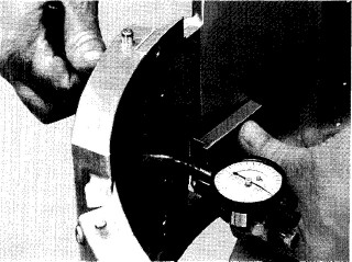
2. Position pre-set slice thickness setting gauge flat against shoe as shown in Figure 32. (See "Adjustments", previous page to set gauge.) Adapter blocks are used between the gauge and the ring on some shredding shoes (Figure 33). Adapter blocks serve to keep the gauge tip-on the peak of the knife corrugation. Slide gauge forward until gauge tip rests on knife edge. Adapter blocks and dowel pin gauges used below are listed on page 73.
Slicing, strip cutting and full shred (.070) heads Ч place gauge directly on support ring.
Full shred (.097) heads Ч Use the 22834 .125 dowel pin gauge block between support ring and gauge when measuring to a knife on a shoe with spacers.
Oval and full shred (.125) heads Ч place the 22133 adapter block between support ring and gauge when measuring to a knife on a shoe with spacers.
Wide oval heads Ч place the 22133 adapter block between support ring and gauge when measuring to a knife on an offset shoe (shoe with most corrugations). Use 22133 adapter block and 22835 .250 dowel pin gauge block together between support ring and gauge when measuring to a knife on a shoe with least corrugations.
3. Turn adjusting screw on cutting head
until the indicator needle comes up to zero. Adjustment to zero should always be on the way in with the screw. If dial goes past zero, back screw out and start over.
4. Rotate head one shoe counterclockнwise and repeat procedure.
5. Adjust three or four shoes past startнing point to cancel out any accumuнlated error.
|
|
|
|
|
Figure 32 Ч Setting slice thickness
|
|
|
|
|
|
|
|
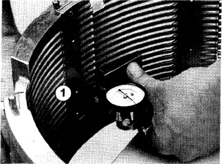
Figure 33 Ч Using adapter block. (1) Adapter Block
6. Tighten screws that hold shoes to
80-90 inch pounds (9.04-10.17 newton-meters).
7. Recheck with gauge to be sure that tightening the screws did not change the setting.
8. Install cutting head, replace lower and upper discharge chutes and rotate feed hopper into position (see "Reassembly", page 43). Cut a small amount of product as a test and measure the samples. If measurement varies from the desired result, adjust setting gauge by the amount that samples were over or under and readjust cutting head.
|
|
|
|
|
|
|
|
|
|
|
|
|
|
|
|
|
|
|
|
|
|
|
|
|
|
|
|
|
|
MAINTENANCE
Impeller Drive Assembly
|
|
|
|
|
|
|
|
REPAIR
NOTE: URSCHEL LABORATORIES URGES ALL CUSTOMERS TO RETURN IMPELLER DRIVE ASSEMBLIES IN NEED OF REPAIR TO THE FACTORY FOR THESE REASONS:
1. Our repair department is equipped with fixtures and equipment specially built for this purpose. Reassembly is done in a special "Clean Room" to minimize dust and dirt contamination.
2. Further damage can occur if the disasнsembly procedure is not done correctly. This is costly to the customer.
3. Potentially reusable parts must be examined and measured to less than a thousandth of an inch. A well-equipped machine shop and skilled personnel must be available to do this correctly. If this is not done, the repair will not be successful and the impeller drive assembly will fail again.
4. Our personnel use their knowledge and experience to not only repair, but also determine when possible the cause for failure. The customer can then make the adjustments in operation to avoid future problems. "Down time" is minimized and repair costs will be less.
|
5. Exchange Program: Because the complete impeller drive assembly is a costly item, many customers choose not to keep a spare unit in stock. In order to minimize down time without having to bear the cost of a new assembly, Urschel Laboratories offers an exchange program. A supply of rebuilt impeller drive assemblies are kept on hand at all times to be shipped within hours of customer's request. The cost of an exchange assembly is based on parts and labor required to restore the customer's returned assembly to acceptable rebuilt condition. For further information contact the service department at Urschel Laboratories (219-464-4811).
NOTE: Exchange program is available in the U.S.A. and Canada only.
If your maintenance department has the skill and equipment and your company wishes to repair impeller drive assemblies, detailed instructions can be found on pages 54-60. Removal and installation instrucнtions are on pages 51-52.
|
|
|
|
|
|
|
|
|
|
|
|
|
|
|
|
|
|
|
|
|
|
|
|
|
|
|
|
|
|
MAINTENANCE
Impeller Drive Assembly
|
|
|
|
|
|
|
|
INSPECTION
Inspect impeller drive assembly for interнnal wear as follows:
1. Disconnect and lock out power source. After machine has come to a complete stop, press the "I" (START) button to verify machine will not start. Remove feed hopper assembly and frame cover.
2. Drive pulley end play must be set properly for inspection, see "Adjustнments", page 53.
3. Rotate shafts. If tight or rough spots are detected, drive assembly should be repaired.
4. Hold drive pulley firmly and rotate impeller back and forth. More than 1/16" (1.6 mm) play measured at outside diameter of impeller means that impeller drive assembly has excessive wear.
5. Check impeller shaft up and down movement. Gripping impeller, pull up and down several times. Any movement indicates bearings must be replaced.
|
|
|
|
|
Figure 34 Ч Impeller drive assembly. (1) Impeller Drive Assembly, (2) Support Plate
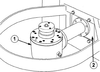
REMOVAL
1. Disconnect and lock out power source. After machine has come to a complete stop, press the "I" (START) button to verify machine will not start. Rotate feed hopper assembly and remove upper and lower discharge chutes. Remove cutting head, impeller, cutting head support and frame cover.
2. Remove motor mounting bolts. Roll drive belts off drive pulley, then slide motor away from belt guard. Remove belt guard and drive pulley.
3. Drain oil by removing drain plug in bottom of gear case. Remove the six (6) screws holding impeller drive housing to support plate. Slide impeller drive assembly out (Figure 34). Generally, it is not necessary to remove support plate.
A WARN ING: Impeller drive assembly is heavy, weighing approximately 60 lbs (27 kg)!
|
|
|
|
|
|
|
|
|
|
|
|
|
|
|
|
|
|
|
|
|
|
|
|
|
|
|
|
|
|
MAINTENANCE
Impeller Drive Assembly
|
|
|
|
|
|
|
|
INSTALLATION
1. Slide impeller drive assembly into support plate. Replace fasteners but do not fully tighten at this time.
2. Place cutting head support on gear case. Use Permatex® Aviation Form-A-Gasket® sealant on fasteners.
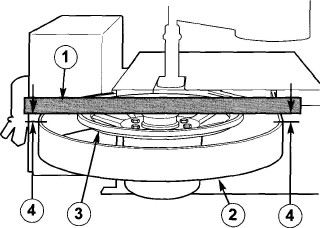
3. Level impeller drive assembly. Place straight edge across top of cutting head support and equalize distance on both sides from straight edge to band on frame (Figure 35). Tighten impeller drive assembly to support plate.
4. Lubricate impeller drive assembly
according to instructions in "Lubricaнtion", pages 40-41.
5. Install drive pulley and adjust pulley "end play", (see "Adjustments", page 53). Install belt guard. Replace motor mounting bolts. Install drive belts and adjust tension.
6. Replace frame cover, impeller, cutting head, lower and upper disнcharge chutes and rotate feed hopper into position.
|
|
|
|
|
Figure 35 Ч Level impeller drive assembly. (1) Straight Edge, (2) Band, (3) Cutting Head Support, (4) Measure
|
|
|
|
|
|
|
|
|
|
|
|
|
|
|
|
|
|
|
|
|
|
|
|
|
|
|
|
|
|
MAINTENANCE
Impeller Drive Assembly
|
|
|
|
|
|
|
|
ADJUSTMENTS
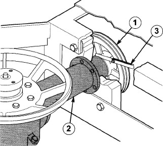
Drive pulley "end play": Set a .004" clearance between bearing housing and drive pulley with a feeler gauge (see "Tools", page 73). Keep shaft pulled out as far as it will go during this adjustment. Tighten pulley set screw, Figure 36.
Motor pulley: Adjust in or out on shaft to align with drive pulley. Tighten pulley set screw.
Drive belt tension: Loosen motor mounting bolts and slide motor. Replaceнment belts must match original belts. Motor pulley must be parallel with drive pulley.
|
|
|
|
|
|
|
|
|
Figure 36 Ч Set end play of .004" between housing and pulley. (1) Drive Pulley, (2) Bearing Housing, (3) Feeler Gauge
|
|
|
|
|
|
|
|
|
|
|
|
|
|
|